
grinder motor drive circuit diagram manufacturer Grasping strong production capability, advanced research strength and excellent service, Shanghai grinder motor drive circuit diagram supplier create the value and bring values to all of customers.
 WhatsApp)
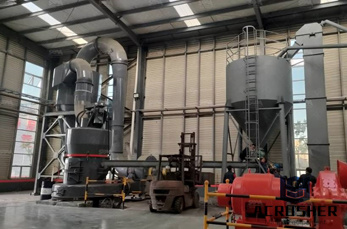
Jul 04, 2017· A Stepper Motor Driver is a circuit that takes the pulse signals from a controller and converts them in to Stepper Motor Motion. In this project, we have designed a simple 12V Stepper Motor Driver Circuit using 555 Timer IC (acting as a controller), a CD4017 Decade Counter (acting as the driver) along with few other components.
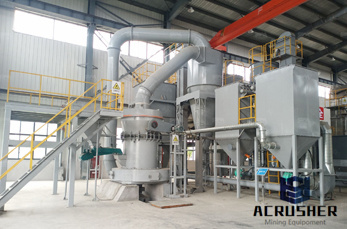
Diagram 1. 5: Saeco Water Tank Magnet (2115) 15: Saeco/Gaggia SJT3 Power Cord (5041) 55: Gaggia Platinum Drip Tray Grate (5246) 56: Gaggia Titanium Grounds Bin . 61: Saeco/Gaggia Brew Unit Screen Holder Key . 68, 69, 70, 107: Gaggia Titanium Coffee Dispenser
Baldor Motor Parts Accessories. Important: When ordering BALDOR internal and external repair parts, it is highly recommended that you confirm the part number correctness. Electric Motor Wholesale does not accept returns on BALDOR replacement parts. Please click on this link and provide the following motor information to confirm the part number needed.
Jan 29, 2019· VFD is the short form of a Variable Frequency Drive or adjustable frequency drive. The frequency determines the motor RPM and by controlling the AC frequency the motor RPM can be controlled. Different types of VFDs are available in the electronics and electrical market ranging from small motor related applications to the high power induction motors.
Output of Inverter/Drive: In long motor lead applications, use reactors (IGBT protected) between the inverter and motor to reduce dv/dt and motor terminal peak voltage. The use of a load (output) reactor also protects the controller from a surge current caused by a rapid change in the load, and even from a short circuit at the load.
Wiring Diagram Book A1 15 B1 B2 16 18 B3 A2 B1 B3 15 Supply voltage 16 18 L M H 2 Levels B2 L1 F U 1 460 V F U 2 L2 L3 GND H1 H3 H2 H4 F U 3 X1A F U 4 F U 5 X2A R Power On Optional X1 X2115 V ... MOTOR 3CT TO 120 V SEPARATE CONTROL * OT is a switch that opens when an overtemperature condition exists (Type MFO and MGO only) T1 T3 MOTOR 3 2 L2 T2 ...
This edition is the most complete available and unusual in showing all the different heads and powerfeed table gearboxes, etc. Covers all years of production and includes all 8 known electrical diagrams (culled from various editions over the years) plus the Quinton Crane Table Drive Motor Instructions and Electrical Schematic.
It is always best to replace both brushes, even if only one is worn. Worn brushes frequently are the cause behind a motor running poorly. Replacing brushes can fix a motor that''s operating intermittently. New brushes can restore a motor''s electric braking. Carbon brushes are one of the most commonly replaced power tool parts.
May 19, 2018· Control of DC Drives Using Microprocessors:The dc motors fed from thyristor converters for variable speeds are being extensively used in general industrial applications. A dual converter, which is a combination of two antiparallel connected three phase
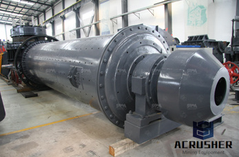
The floor grinder is a sturdy, reliable and easy to use machine. The floor grinder is fitted with a hp single phase motor. This motor offers a direct drive to the grinding plate by way of a flexible coupling between the motor and the plate. The shroud system is unique in design by automatically adjusting to suit segment height and floor angle.
Chapter 6: Parts Lists and Schematic Diagrams Parts List HANDLEBAR ASSEMBLY NOTE: Part numbers listed are available through DR Power Equipment. Ref# Part# Description Ref# Part# Description 11238 Washer, Flat, 1/4" 16495 Grip, Ergonomic, 1" 11158 Bolt, HCS, 5/1618 X 1, ZP...
Feb 23, 2020· Your circuit diagram is ok. I added 7812 for 12v for circuit section. 24v for motor. The mosfet I used is 50n06. At present I don''t have a 470mfd or more value with voltage rating greater than 25vdc to try parallel with will try once I get it. My problems started after I connecting the 470mfd to drain and source.
Nov 18, 2016· The line reactor can help to protect from transient voltages and reduce harmonics to or from the drive. Keeping the loadside—output—wiring less than 75 ft between the drive and motor, or using a loadside reactor, can help to reduce the potential insulatedgate bipolar transistor (IGBT) reflective wave damage.
circuit, however, the wiring diagram does not show the connections in a manner that can be easily followed. For this reason a rearrangement of the circuit elements to form a line diagram is desirable. The line diagram (sometimes referred to as an elementary diagram or a schematic diagram) is
D28110k Grinder Parts (Type 1) D28110 Grinder Parts (Type 1) D28065 Small Angle Grinder Parts (Type 1) D28065N Small Angle Grinder Parts (Type 1)
Notes: This circuit is known as a latching circuit, because it "latches" in the "on" state after a momentary action. The contact in parallel with the "Run" switch is often referred to as a sealin contact, because it "seals" the momentary condition of the Run switch closure after that switch is deactuated.. The followup question of how we may make the motor stop running is a ...
ACCUPro SpinRelief Grinder Manual Controls 115 230 VAC. Operator Manual English 0908. ... Wiring Diagram (Coming Soon) 620 Documents. Owners Manual 0414. Wiring Diagram 0510. 618 Grinder Documents. ... Traverse Drive Instructions 0711. Reel Setup Gauge 1113.
8. separately excited DC motor drives a large grinder machine in a A 100 HP, 500 Vdc paper making factory. Motor losses are equal to 12% of its rated power. (IHP746 W). The motor turns at a nominal speed of 600 rpm when CEMF Eo470V. Excitation voltage is V 100 Vdc. (a) Simply draw the field and armature circuit wiring diagram.
4: Gaggia MDF Grinder Motor: 120V (2573) 10: Gaggia MDF Burr Set (1688) 14: Gaggia MDF Grinder Bean Hopper (1873) 15: Gaggia MDF Grinder Bean Hopper Lid (2498) 24: Gaggia MDF Doser Lever Spring (1889) 29: Gaggia MDF Grinder Switch (2657) Note: Compatibility can vary at any time, please contact us if you are uncertain which part is required.
These diagrams are current at the time of publication, check the wiring diagram supplied with the motor. *NOTE: Refer to the motor manufacturer''s data on the motor for wiring diagrams on standard frame Ex e, Ex d etc. motors. Inst Maint 5/03/2008 10:02 AM Page 6
Simply spinning the drive shaft makes the grinder run. The step pulley system allows 3speed choices, fast, med and slow. The 4", 3" 2" pulley is used because the centerline distance between the motor shaft and grinder drive shaft is the same for each belt position. This eliminates the need to readjust the motor position for each speed ...
Project report on wet your whiskers electrical circuit diagram of mixer grinder for kitchen class diagram for remote dekstop connection connection diagram of a desert cooler wet ash disposal system electrical wet grinder motor wiring diagram9611samsung gt e1207y white display jumper connection diagram of swinburne s test .
Industrial Grinders, Buffers, Accessories Replacement Parts; NEMA Motors Product overview; US DoE Integral Horsepower Motor Rule for low voltage motors
Aug 12, 2019· I think motors You are using in USA with grinders are 3 phase motor modified by this way. From diagram You can calculate for 2 HP motor it is cca 210 uF (need few tests around this capacity). This is useful when he think about VFD in near (or not so near) future. EDIT: here is something about it in english
WhatsApp)